2015年11月28日星期六

ARCH 653 Project 2 _ Dynamic Shading

ARCH 653

Dynamic Shading


1. Purpose of this project
First, I plan use Dynamo to rebuild the model of Project 1. Second, I will build the dynamic shading which shapes can be changed by Dynamo and Sun Path. And test how to change the angle of dynamic shading devices to control the direct sunlight.  

2. Building Mass on Dynamo
2.1 Outline Curves
I built three curves in Revit, and then, transfer these curves into Dynamo by "Select Model Element" command. This process shown in Figure 1.


Figure 1: Transferring Curves from Revit to Dynamo

2.2 Point on Line
First, I built a range of points along Z axis. And then based on these point built several planes. Finally, the use of intersection commend found the adaptive points on curves. This process shown in Figure 2, 3.  
Figure 2: Dynamo Command for points on curve
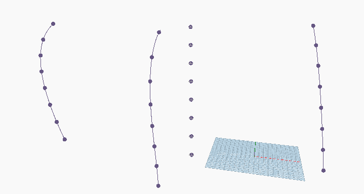
Figure 3: Adaptive points on curves

2.3 The use of family build the floors.
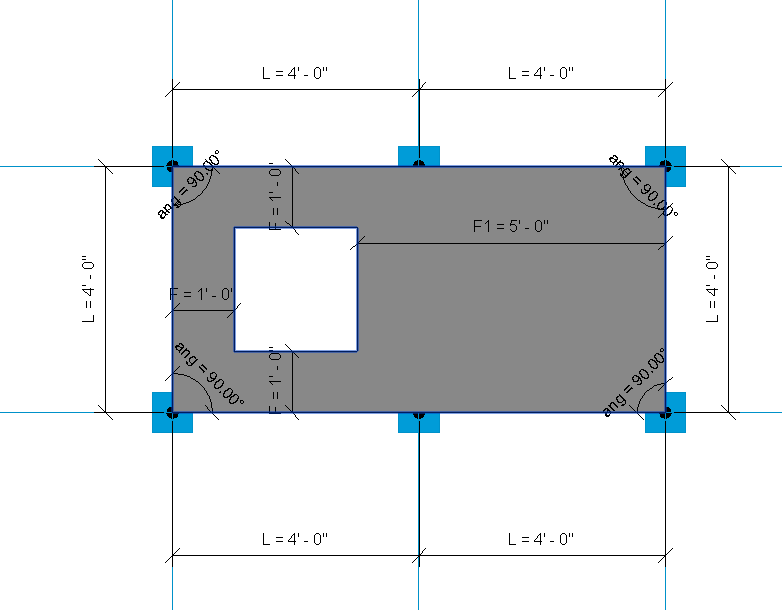
I built the family_Plan controlled by three adaptive points in Revit, which shown in Figure 4.

Figure 4: Family_Plan
The "family types" command could load the plan family into the Dynamo. Based on the adaptive points, this family can be applied to form the floors. This process shown in Figure 5,6.
Figure 5: Load family into Dynamo
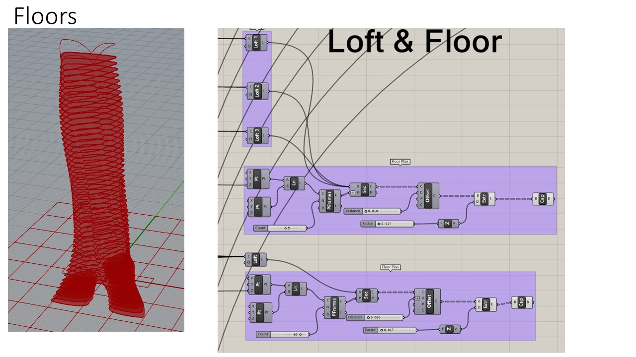
Figure 6: Floors

2.4 Building facade.
I used the "Surface By Loft" command to form the surface, and then used the UV Quads command to find the adaptive points on surface.The number of adaptive points can be controlled by integer sliders. That process shown in Figure 7 and 8.
Figure 7: Dynamo about how to build building surface curtain 

Figure 8: Adaptive points on surface


I built the family_curtain for building facade curtain. The family frame can be controlled by U_Grid and V_Grid. It shown in Figure 9.

Figure 9: Family_Curtain

And then apply this family into facades based on the adaptive points, it shown in Figure 10.

Figure 10: Building Curtain

3. Dynamic shading
3.1 Shading Family
I built the shading family that controlled by the Rotation_Top, Rotation_Center, and Rotation bottom parameters. It shows in Figure 11. When the Rotation_Top=Center =bottom=0, the shading shape shows like Figure 12. When the Rotation_Top=bottom=90, and Rotation Center=0, it shows like the Figure 13.

Figure 11: Shading Control Parameters

Figure 12: Rotation_Top = Rotation_Center= Rotation bottom =0
Figure 13: Rotation_Top = Rotation bottom =90, Rotation_Center = 0


3.2 Loading the shading family into building facades.
The use of family types and surface adaptive points apply the shading family on building facades. This process shows in Figure 14 and Figure 15.
Figure 14: Shading Command on Dynamo

Figure 15:Shading Devices 
3.3 Shading shape changes by rotation angle
I use the "Set Parameter by Name" command to change the parameters on family. The integer slider is use for controlling the shading rotation angle. It shows in Figure 16 and 17.

Figure 16: Shading shape control sliders
Figure 17: Shadings


4. Change shading shape with the Sun Path
4.1 The shading open and close
There is an angle between panel normal and sun direction. When the angle is close to 90 degree, the shading will open (shown in Figure 18).
Figure 18: Shading Open
When the angle between panel normal and sun direction is close 0, the shading will close (Shown in Figure 19).
Figure 19: Shading Close
4.2 Find the panel normal vector.
Based on the surface adaptive points, I found the panel normal vectors. The Figure 20 shown the process how to find the panel normal vectors.


Figure 20: Panel Normal Direction Process
Figure 21: Panel Normal Directions
4.3 Sun Direction
I found the sun direction by sun setting command in dynamo,which shown in Figure 22.


Figure 22: Sun Position Setting
Figure 23: Sun Direction
4.4 The angle between sun direction and panel normal direction
The use of the angle between vectors command to find the angle between sun and panel normal directions.(Shown in Figure 24)

Figure 24: Angles between sun direction and panel normal direction
I set these angles as the input to control the shading rotation.(Shown in Figure 25)

Figure 25: Angle Control the Shading shape
4.5, Sun Position with the shading changes
If I changed the sun position, the shading angle will change(Shown in Figure 26).

Figure 26: Sun Position and Shading shape

5. Video


2015年11月2日星期一

ARCH 653 Project 1_Parametric Design of Major Cultural Center in Albania

ARCH 653

Parametric Design of Major Cultural Center in Albania

1.       Background
These buildings are designed by BIG, it is a 27,000 m2 cultural complex in Albania, consisting of a Mosque, an Islamic Center, and a Museum of Religious Harmony.

Fig 1 Major Cultural Center in Albania

2.       Analysis of the Geometry

Fig.2 The Concept of Original Building Box


The original shape of these three buildings is quadrangle boxes. One of these building was twisted from bottom to top. Other two was subtracted by a model.         


Fig 3 The Transformation of the Building Shape

3.       Parametric Mass Generation.

I built this mass by using a Conceptual Mass Family. I used the reference points to build the reference lines. And these reference lines could be changed by moving the position of points. I copied these reference points and lines to other levels in order to get the mass structure.


Fig 4 Reference Points


Fig 5 Four Levels of Reference Lines

By moving the reference points, I could get any shape I want. And then, use the “create form” command to build the shape.


Fig 6 The Changes of the Moving Points
Fig 7 Building Mass

I set a parameter of height. If I change the height value, the building shapes will be changed. 

Fig 8 The Parametric Setting of Height

Fig 9 Height=10 ft

Fig 10 Height=20 ft

Fig 11 Height=30 ft

4.       Curtain Panel:
From the following image, we could see that: the windows are not in the same row. These pattern like the chess board, but not exactly the same pattern. 

Fig 12 The facade pattern
4.1, In order to build these window patterns, I selected the 1/2 step curtain pattern. And then open a window controlled by the offset parameters “F”. 
Fig 13 The 1/2 Step Curtain Pattern

Fig 14 The Parameter Setting of the Curtain Pattern

Fig 15 The Finally Shape Of The Curtain Pattern
4.2, Form figure 14, I set the panel with materials: glasses and wall.

5.       Loading the Curtain to the Mass

Fig 16 The Final Image
6.       Render Images
7. Video


ARCH 655_Project 1_Parametric design of LAVA Snowflake Tower

1. Background.
This is a project by LAVA - Laboratory for Visionary Architecture and it is located at Abu Dhabi, United Arab Emirates.  Reference: http://www.l-a-v-a.net/projects/mswct-snowflake-tower-2/
LAVA Snowflake Tower
1.1 The parametric definition is based on the concept of a "Snowflake". The facade has some pillars.
This floor plan picture showed the main idea that how to form this "snowflake" shape.
Geometry Analysis

1.2 In order to form this building, I should build these six varied floor plans, and then use the loft command to form this kind of building shape.

2. Parametric Floor Curve Generation
Concept of Floor Plan


2.1, There are five groups of control point to form this floor shape.  The group P1 are controlled by three circles with radius; the rotated angles between these three circles are 120. Group p2 are similar with the group 1. Group p3, p4, p5 are used to control the curvature of curves.
Point Group 1

2.2, In the Point Group 1: Firstly, set one point controlled by "Y unit vector", and then rotating it in 120, and 240 respectively to get other 2 points. Secondly, Set these three points as the center of three circles with the radius R1. And R1 is controlled by a slider. Thirdly, using the "point on curve" command to get two points on a circle.
2.3, Used the similar method to set the Point Group 2.

Point Group 3

2.4, In the Point Group 3: I set one point controlled by X coordinate, and then rotate it to get other five points, the rotated angle is 60 respectively.
2.5, Point group 4, and 5 are used the similar method of point group 3. 
Curves Forms
2.6, Used the "interpolate curve" command to form 6 big curves; and six small curves. And, the big curves will be used to build the facade pillars.

2.7, Therefore, the main shape of the "snowflake" plan is controlled by the parameter p1, r1, p2, r2, p3, p4, p5. 

Changed these 7 parameters, we could form the other 5 varied floor plans. And then used the “Z coordinate” parameter to control the height position.  

Besides these 6 varied floors, I used the similar method to build the other two plans: -1 varied floor and 7th varied floor, to form the building base and the roof structure. 

3. Building Facade Generation and Analysis
3.1 Used the "loft" command to form the facade.
Building Facade
3.2 Physically-based model analysis: Add the springs and U-Force to test the effects of wind direction and gravity on the shape of the facade.  Set "z coordinate slide" to control the gravity effect, and set "x and y coordinate" slide to control the wind direction.
Physical Force Analysis

4. Floors
Used the “Brep plane section” command to building the floors. The number of floors controlled by the count slider of “prep frames” command. Then, use the “Cap Holes” command to form the floors.

5. Facade Pillars: Data Structure
5.1 Facade Pillar Control Curves
This process could be tricky. In order to simplify this process, I used the data structure to organize it.
First, As I mentioned before, the pillars is on the 6 big curves of each floor. On each varied floor, the first step is used the “Divide Curve” command to get the points on the 6 curves.

Second, these Points are a tree structure with 6 branches. However, I did not want this kind of data structure. Hence, I flatten them into the single list.
Third, after I got all the points on total 8 varied floor curves, there are 8 separate lists of points. I used the entwine command to combine these 8 lists into a tree structure. We can see this tree has 8 branches, and each branch has 42 points.
Fourth, However, this kind of data structure cannot help me to form the curve that I wanted. Hence, I used the “flip matrix” command to reorganize the data structure. This tree structure has 42 branches, and each branch has 8 points. And then, Used the interpolate curve command to get the façade pillar curves. 
5.2 Pillars
First, Built the rectangles on the top and the bottom of the pillar control curves. 
And then, Used the "Sweep 1" command to form the pillars with the facade curves and top & bottom rectangles.

6. The Render Images


7. Video Link